The phenomenon causing 2022 F1 cars to bounce down the straights is known colloquially as “porpoising”. Behind the scenes, teams of experienced aerodynamicists are working quickly to find solutions. Many have asked: how did they miss this issue?
With the growing accessibility of basic CFD aerodynamics simulation testing, more people are trying their hand at vehicle aerodynamic development; accordingly, this is an opportunity to discuss some of the critical points in aerodynamic design. The concepts involved are important both in and outside of Formula One. I hope this article will be of interest to those of you who are enjoying aero as a hobby and serve as an interesting read for those who follow it as a curiosity.
To introduce myself, I’m Andrew Brilliant, the director of AMB Aero, an aerodynamics consulting firm based in Sapporo, Japan. We utilize both in-house 40 DP-TFLOP super-compute CFD and physical wind tunnel test facilities. My mentor and partner Yoshi Suzuka was a major contributor to the modern understanding of underbody tunnels. His work shaped them from the early F1 style ‘underbody wings’ to what would later become known as the modern ‘venturi’ style during the development of Nissan GTP cars. At AMB Aero, we have been fortunate enough to develop all sorts of cars – especially many race cars – all over the world. Thanks to classes like IndyCar, LMP, or even Hill Climb and Time Attack that never fell victim to the ‘flat floor dark ages’. We have completed more than ten thousand CFD and wind tunnel tests for tunnel cars alone. By way of relevant contrast, we also have completed work more recently in modern F1, which gives an interesting perspective from which to observe current F1 performance trends.
“Ground effect” was discovered by accident
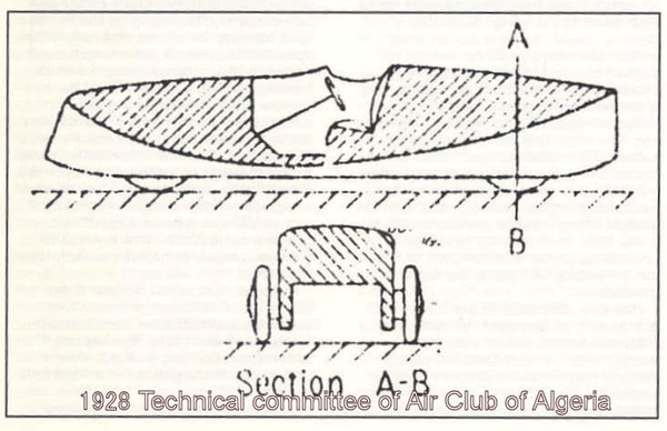
In the late 1970s Lotus first discovered this phenomenon when their wind tunnel model was not sufficiently rigid resulting in the side pods sagging closer to the ground. As they did, downforce increased sharply. Lotus engineers then sought to understand this phenomenon and in doing so determined to close the sides of the floor, leading to the now-famous ‘sliding skirts’ (that were subsequently banned).
So powerful was this ride height effect, that after banning skirts, a car was run with completely solid suspension. In this infamous test, the driver commented that the car was quicker set low and solid, but he struggled with vision and vibration. The driver asked for a padded seat and was jokingly suggested to sit on his wallet. Fast forward many years later and even without tunnels, Formula 1 and many other disciplines have far exceeded the total downforce of F1 in those days.
The concept of designing-in ride height sensitivity became deeply rooted in modern racecar aerodynamics. Generally, cars are run close to the ground to maximize underbody downforce (among other reasons), and accordingly – much as Lotus found in the 70’s – it is incumbent on designers to manage this ground effect phenomenon towards a net performance advantage.
“Ground effects” is a dated term
In the early days, it was believed that the ground effect (Wikipedia) acted similarly to the known behavior of airplane wings wherein lift increases with proximity to the ground. You may have even felt this during a landing as if the plane is somewhat ‘cushioned’ in late descent with the pilot adjusting controls until touchdown. It was thought that we were experiencing the same phenomenon with downforce-generating (inverse) wings with downforce increasing with ground proximity.
Many years later, we would come to understand some differences with ground vehicles and that the proximity of underbody wing forms is not the major cause of extreme sensitivity to ride height. At AMB Aero we call them underbody tunnels. In our experience at AMB, this sensitivity is primarily due to changing flow field resulting from the relative position between the tire and the sprung body of the car. In the case of Formula cars, this can be conceptualized as the position above vs below the floor. Or for a closed wheel car, a tire is more or less shrouded inside of a wheelhouse.
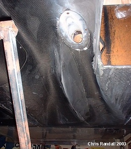
Enter the era of Group C
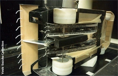
This early prototype imitated the simple “underwing” concept and eventually evolved into the shape of Yoshi Suzuka’s Nissan P35 in the early 1990s. This along with many aerodynamic improvements took thousands of wind tunnel tests. The downforce generated was elevated to the stuff of legend. The complexity of flows involved in F1 has grown ever more intricate.
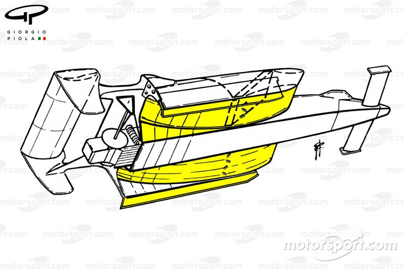
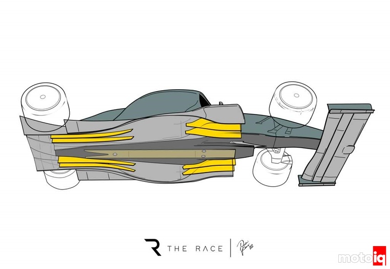
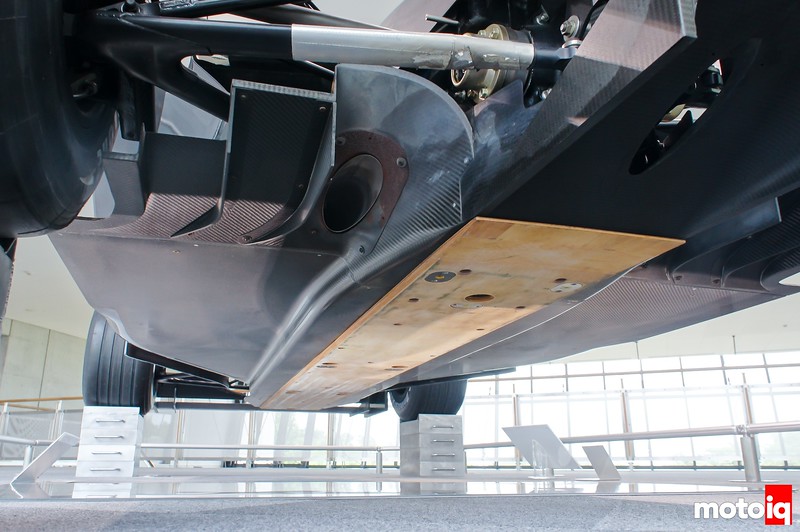
As you can see below, the modern Formula 1 car tunnel is closer to a “Venturi” type, unlike those early ‘wing style’ F1 side pods.
Formula 1 aerodynamicists are not the first to experience this phenomenon through F1 attracts so much more attention as early testing is very public. We have supported prototype and even Time Attack customers with similar issues through to resolution. It is definitely not uncommon, in most categories it can be avoided through the careful use of CFD and wind tunnel testing.
Admittedly it is a far more difficult problem in F1 given the complexities of vehicle forms and the performance margins sought. This said, given the number of skilled people and the quality of tools available I am confident the problem will be solved quickly. We may even see evolving solutions over the course of the season and clean slate solutions next year.
All things seek equilibrium
On any car with aerodynamic downforce applied to a suspended mass (the tire’s spring rate also being a form of suspension), the car will always find a state of equilibrium; the ride height will compress until springs support the aerodynamic forces. As speed increases, so does downforce – the ride height will decrease increasing downforce again.
Porpoising is bouncing or oscillation in front, rear, or both caused by a loss in downforce at some ride height resulting in downforce being lost. Once downforce is lost the suspension springs then return the car to a higher ride height, however in this position the flow field again generates additional downforce and restarts the cycle.
Rear porpoising is what you have seen on the Formula One cars this year, but front-only oscillations can happen too. The term ‘porpoising’ came from the early designs where the front wing was extremely sensitive to pitch change; an appropriate change in rear ride height caused front downforce to increase subsequent to the rear rising. This back-to-front bouncing resembled a dolphin coming out of the water nose-up and dipping back under with the nose down over and over.
Downforce isn’t a number, it’s a map
The real cause of porpoising is better described as what aerodynamicists term as a ‘sensitivity’. There are lots of sensitivities and in this case, the relevant one is ride height, being the distance from an arbitrary point on the car to a point on the ground. One of the most basic tools we use is called an aero map, a graph visualizing an aerodynamic behavior of a car. It is a simple 3D graph to visualize the behavior of a car, in this case, ride and pitch sensitivities. The bottom axes are front and rear ride heights. You might visualize this like a fuel map in your ECU where engine RPM is plotted against manifold pressure or volumetric efficiency used to create a three-dimensional graph of the fuel delivery requirement.
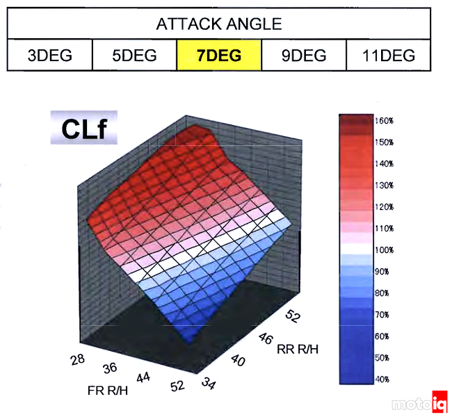
It is easy to see from a map like that just how irrelevant and limiting a single value for downforce or drag can be. Aside from the huge variance across speed ranges, you could pick a number for downforce at some ride height you would never see in a corner (where downforce is helping you go quicker) or at some wing angle that would make you under-steer straight off the track. Asking the downforce of the car is like asking what is the altitude of Europe? Are you in the Swiss Alps or on a Mediterranean beach? The question needs important context for a correct and relevant answer. The most basic tool of all is the ride/pitch aero map and you need a graph like this for front and rear downforce as well as drag. These are a must-have to ensure proper and safe development. Enabling teams to maximize aerodynamic force interaction with the suspension, as you see above, is a big deal.
If you want a picture of the severity and extremity of aerodynamic behaviors against sensitivities blow-overs can paint a clear picture. This modern Toyota prototype gains enough lift through a yaw sensitivity to pick the car up off the ground when otherwise in a straight line it would have many tonnes of downforce at speed (as its designers had intended):
Or the infamous back-flips of the Mercedes and Porsche GT1 cars when flat floors were first regulated in the 90s. This is extreme pitch sensitivity.
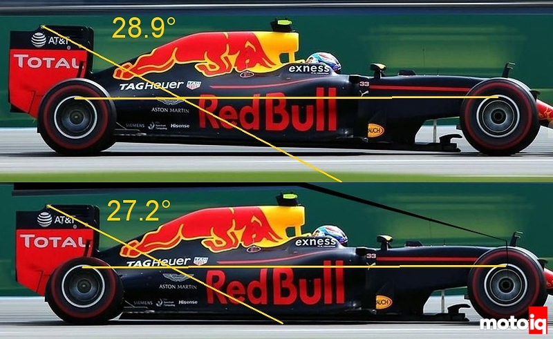
Tunnels are far safer than diffusers in this regard as flat floors suffer from much higher pitch sensitivity than tunnels. A tunnel car can see larger negative pitch angles before lift is achieved. From this perspective, a tunnel may even be considered a safety device when compared with a flat floor. It also offers a cleaner wake to promote exciting racing by lessening aerodynamic losses to the car following behind.
In reality, when cornering your car will be experiencing several degrees of freedom. In roll, what is the ride height when the outside edge of the splitter is on the ground and the side facing inside the corner is lifted higher than static ride height? Or yaw – where cars are sliding at significant angles any time you are cornering. The steering angle is another major variable. For simplicity in this article, we will focus on ride height/pitch and save yaw, steer and roll for another time.
Diffuser cars also porpoise
Any underbody device can be prone to porpoising. It is just a question of ride height, if you see a drop in downforce through the ranges it will experience on the track. Any car with sufficient downforce and speed can do this.
With a diffuser car, the contribution to total downforce is less, so the reduction in tire effect on the underbody can work for or against you depending on the design. F1 had its fair share of issues in the early flat floor /diffuser days, some of which weren’t resolved for a much longer time than we see teams sorting porpoising out this year. The lessons learned contributed to the modern level of safety with the rate of driver injuries and deaths trending downward over time.
The porpoising seen this year is a relatively mild phenomenon resulting only in reduced lap time and (possibly) driver discomfort; drivers can simply reduce speed when it starts. The sudden behavior of something like a blow-over/vehicle flip will be completely unstoppable. Understanding has advanced much and problems like this have become increasingly rare and less severe.
What is happening under the hood?
A modern ‘venturi’ style tunnel can be imagined as three components: the volume reducing throat section, followed by the minimum diameter nozzle section, and lastly the expanding diffuser section. Porpoising likely begins late in the nozzle or diffuser where flow velocities are higher and adverse pressure gradients can easily lead to flows abruptly detaching from the diffuser wall: the velocity through the tunnel will then be reduced, underbody surface pressure rise, and downforce drops off sharply.
Many of the explanations of porpoising causes are simplified, some citing “less effective” floor sealing vortices as the culprit however in reality while that is not necessarily untrue, flows around any part of the car (particularly underbody surfaces) will be optimized for some ride height and is likely to lose downforce at other ride heights.
Aerodynamic solutions
Modern racecar aerodynamics –particularly in Formula 1– are complex systems; without looking in detail at CFD or wind tunnel data it would be impossible to definitively know the probable causes of a specific car. It could be that Ferrari’s wide side pods help produce higher-energy and better-directed flow into the tunnel throat. Mercedes uses a narrow side pod, perhaps this leaves them heavily dependent on a rear beam wing being more vulnerable to rear ride height effects. Or the ‘floor sealing’ vortices could be at fault as many have suggested, but I can see that happening in both the way suggested and the complete opposite.
For example, let’s say you made the ‘floor sealing vortices’ less effective, introducing more turbulent flows to the diffuser at low ride height. You may have stabilized a situation between low and high ride height performance: what was once an overly-aggressive geometry for low ride height now continues to function without decay. Conversely, you could concentrate on the floor sealing vortices being more effective at high rear ride height. That will increase performance at high ride but also converge the optimum geometry between high and low ride. Complementing strong performance at low ride again reduces a relative performance decay between the two kinematic states. So both “better” or “worse” floor sealing vortices can stabilize behaviors across ride heights depending on how you define them. Which choice will result in a higher or lower performing car overall might follow a trend, but there are no absolutes given the complexity of a total package.
In not being a fly on the wall inside all the teams, I am left with more questions than answers. Each team will map out their best ideas and test them until they find the least compromised solution. Looking at the changes made up until race day or into the first few races may provide further clues.
Often in practice, you don’t need to change the tunnel behavior necessarily. A modified geometry on any part of the car could potentially change the performance trend. The outboard rear floor edge for example could be designed to produce more downforce on the top side with lower ride height. Many other examples exist, if you can stabilize the total forces on the suspension through the vehicle’s attitudes of interest, you solve the problem. As the challenge involves solving for a range of downforce outcomes across many vehicle attitudes the best overall solution can sometimes be a compromise between various aerodynamic systems and surfaces producing more or less downforce as needed to allow flows through the tunnels to be optimized across relevant vehicle conditions.
Heave stiffness, the nuclear option
Of course, you can avoid all this by simply cranking up the suspension heave (vertical spring) stiffness until the car no longer gets close enough to the ground. This, however, comes with a cost, the added stiffness will likely compromise performance in other parts of the track. Additional heave increases the propensity for sudden loads into the tires reducing grip, shortening tire life, increasing tire failure risk, increasing tire temperatures, and more drag. In addition to all this, the heave spring will be at a progressive rate and so damping is a compromise between low and high rates. Leaving the car under-damped and more prone to porpoising without even further handling compromises.
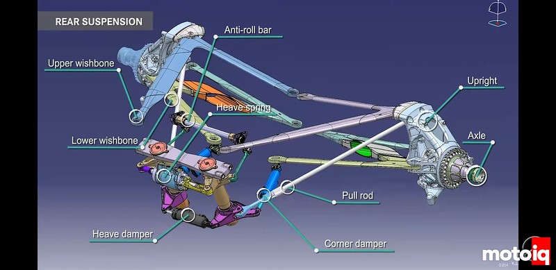
At the top end of motorsport, a team of engineers are pouring over aero maps, simulations, and making tiny adjustments to milk the aero map utilization. These small gains in downforce can have an enormous impact on lap time against the rest of the field in a sport this dependent on aero. Putting the car into a constrained attitude mechanically just to survive down the straight is not an easy pill to swallow: best compromises in vertical spring forces are so important that modern F1 suspensions employ a dedicated heave spring.
The difficulty of replicating low ride heights during development
Whilst every team likely foresaw this risk some may have under-estimated it. At any rate, there exists some difficulty in replicating the situation during aerodynamic development.
A Formula One car on the circuit will often come into contact with the ground on the straight. The rest of the time near top speed it will be very close. The better job you do at walking this fine line, the quicker you go. This is difficult to replicate in aerodynamic testing. The central skid or plank is the absolute limit to minimum ride height. That also means that where many other motorsports must control their ride height to keep from destroying the aero, an F1 car will impact the plank and survive. Sparks flying are an indication that the car has made contact with the ground.
Modern wind tunnels utilize a moving belt floor and a model suspended from the roof by a device called a sting. The rotating tires are supported from the sides or by carefully designed attachments to the car that isolate it from the belt vibrations. The moving belt floor below the car is spun by large drums. The model of the car is equipped with extremely sensitive instrumentation both inside the model and in the sting.
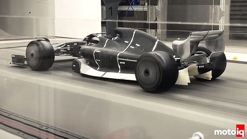
If you intend to produce a winning car at the level of F1 you are accumulating tiny gains and performing thousands of tests. These devices need a stable platform that is vibration-free and measures the smallest possible values with pinnacle repeatability, taking hundreds or thousands of measurements, high accuracy, and low variance results of forces and pressures.
Real-world running on race tracks is, by contrast, very different. It’s a noisy, rough business with vastly different instrumentation requirements. The car is not held between static positions, it moves fluidly – sometimes violently – between kinematic extremes at high speeds and rates of change. Whilst the data we receive from race cars is not as resolute as what we see in a wind tunnel, it is contextually accurate. Pressure sensors indicating e.g., that a critical component of the underbody is stalling in a given instant is real, and ultimately lap times are what we are engineering for. Porpoising is difficult to replicate in the wind tunnel, in part for a variety of technical factors (most wind tunnel tests do not replicate the full scale or full speed of racing conditions) and in part, because tunnel testing faces significant challenges in trying to recreate dynamic vehicle conditions – a wind tunnel model does not bounce on its own suspension.
There are other practical limitations. The wind tunnel belt – much like the belts you know driving the accessories on your own car – cannot be set infinitely tight without risking failure. Despite operating typically on many tons of tension it invariably has some slack, and suction is used to keep it in place – but the test model car underbody, in creating suction, exerts a lifting force on the belt. This is one reason a minimum gap to the floor must be maintained in wind tunnel testing, there are many others that contribute to a key departure from conditions seen on track. We have designed and built wind tunnels for manufacturers and this is a small fraction of the technological challenges. Money can solve a lot, however, no matter what sort of tunnel you are using, the test method involved has practical limits needing to be understood. On-track validation won’t be going away any time soon.
Computational Fluid Dynamics (CFD) uses well-established formulas to predict the behavior of air around a test article though similarly has limitations of its own. Most codes break down the air volume around a vehicle into a series of units of various sized discretized volumes known as the ‘mesh’. The ‘mesh density’ refers to the size of these blocks; in general, increasing the mesh density increases accuracy at the expense of computing resources. To avoid an arms race around supercomputing resources, what teams are allowed is regulated, with allowances being relatively low against large supercomputers – just a few years ago F1 was limited to 25 or 30 double-precision teraflops (TFLOPS), which is less than our office sized Intrascale™ “Nimrod” cluster. Compute allowance is based on finishing results in the championship – teams at the back of the grid are incentivized with more resources: compute usage is even more precious to winning teams.
At any rate, the mesh density used for Formula One is more than twice as fine as typically utilized for road car development due to the immense complexity of an F1 car. The mesh density is carefully controlled, not just for accuracy vs compute compromises but also to ensure a stable result across all tests, high and low ride heights included. As the car approaches the ground, clearance can become so small that the mesh density becomes insufficient to accurately predict the behavior of the flow. One could simply increase the mesh density but the computing requirement increases as an exponent of this size, and large variances in mesh density can make comparative results against other mesh density tests inconsistent, creating resource requirements that are unfeasible for complete development processes where all simulations run with such high mesh densities. An actual ground impact simulation may need a completely different strategy – one that would require physical validation work to yield processes as robust as those teams will have spent years refining.
And again, CFD simulations are typically static assessments of how a vehicle might perform: a ‘freeze frame’ view of flow around a vehicle that in practice moves very quickly through time and space, with that movement complicating the flow field around key aerodynamic surfaces. The bleeding edge of research in CFD is very, very evolved. Is it theoretically possible to run a CFD simulation of a vehicle actually porpoising? Yes, though the computational requirements would dwarf anything teams might otherwise do in a resource-capped environment, which would take away valuable development resources from typical vehicle performance development: in short, a team might be able to do it, and they might get a detailed insight into or even solve porpoising this way, but a trade-off is made in terms of testing and time. Those decisions are made months before any on-track testing is done and while the rest of the vehicle development is still evolving.
As ever, the truth lies in track behavior. We find ourselves again dependent on real-life testing.
What can mere mortals do in developing their own car?
For most platforms real-world behaviors match the CFD or wind tunnel predictions within ranges you can test. Few disciplines outside of F1 and LMP run at ride heights low enough to be out of range for CFD or wind tunnel environments (running that low would damage the vehicle in a handful of laps without a large consumable plank as in F1). Similarly, few disciplines are so regulated as to run designs with aerodynamic performance so extreme yet with performance margins so slim as to create a propensity towards porpoising across an entire vehicle category at the first track tests after a regulation change allowing underbody tunnels.
As you progress toward making enough downforce to experience porpoising you firstly rely on those CFD or wind tunnel tools, iterative design and testing across ride and rake will prepare you for the problem. If you are simply testing on track, the good news is that by nature you are testing across a range of attitudes. The disadvantage is that this is a test method with a far worse signal to noise, though this may be sufficient for basic development in lieu of competitors correctly applying deeper development resources. An amateur correctly applying the basics and testing only on track is quite unlikely to have this sort of issue.
For those using CFD aerodynamic simulations or wind tunnel
Peaks and valleys in the aero map should be found and smoothed out. You will need to optimize some part of the car to function differently in the ride height regime where the problem occurs. There are no magic bullets and each car will be case by case. The CFD tool itself will not tell you how to solve any problems. Your intuition, learning from each result and raw iteration count in design is the best way forward, particularly where study and interrogation of each result can be used to give you a detailed understanding of how various aerodynamic systems perform enough to provide you with knowledge towards options in aerodynamic configuration tuning complete vehicle designs to alleviate performance issues.
Looking forward to solutions from Formula 1 teams
I am very much looking forward to studying the various anti-porpoising approaches employed and testing them for myself. This continuing quest for knowledge and understanding is core to all aerodynamicists. I genuinely enjoy working with the experimentation inherent in modern vehicle aerodynamics, and I hope you will enjoy watching this most interesting 2022 F1 season as much as I will.
Andrew Brilliant, AMB Aero.